Portfolio

projects
Capstone

Mechatronics Maze Solving Robot
Problem
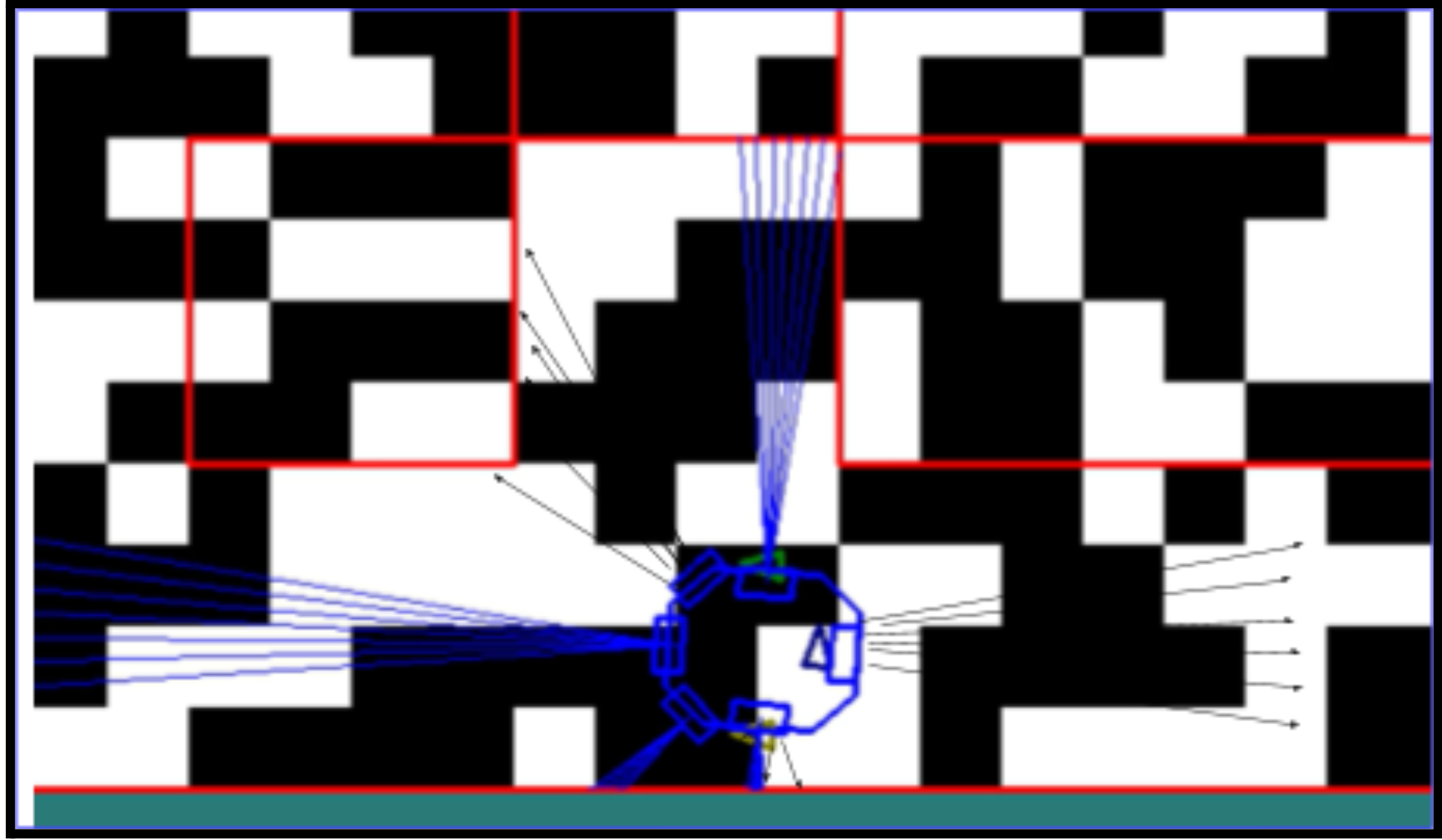
The project required designing and constructing a compact rover capable of navigating a predefined maze while meeting strict constraints on size, weight, cost, and functional requirements. The rover needed to avoid obstacles, localize itself anywhere in the maze, pick up a block from the loading zone, and deliver it to a specified drop-off point, all while operating at SAE Level 2 driving automation. Additional challenges emerged throughout development, including unreliable ultrasonic readings at angled walls, motor bias affecting straight-line motion, power limitations, and the need for a stable, user-friendly control interface.
Method
To solve these challenges, the team implemented a multi-milestone, iterative strategy. First, they developed automated obstacle-avoidance logic in simulation using ultrasonic sensors positioned around the rover to detect the longest clear path and execute angular turns when walls approached. Next, for real-world localization and navigation, they switched to manual operation supported by Bluetooth communication, a compass for orientation, averaged ultrasonic readings, and a printed maze map. They then upgraded the control system using two Bluetooth modules—one dedicated to motors and one to sensors—allowing simultaneous movement and real-time sensor visualization through a custom Python interface. Mechanical and electrical systems were redesigned extensively: the chassis footprint was reduced to improve maneuverability, threaded rods were added for modular height adjustments, a buck converter stabilized power delivery, and a PID controller corrected motor bias. Finally, the team iterated through multiple gripper mechanisms before developing a single-servo “X”-shaped arm that reliably swept the block into a catch tray.
Solution
The final rover successfully integrated mechanical, electrical, and software systems into a compact, stable platform capable of completing all milestone tasks. With improved ultrasonic sensor placement, PID-stabilized driving, modular chassis architecture, real-time sensor visualization, and an intuitive gamepad control interface, the rover achieved consistent localization, maintained safe distances from maze walls, and executed precise navigation. Its simplified and optimized gripper mechanism allowed for reliable block pick-up and drop-off, and the complete maze task was finished in 4 minutes and 18 seconds, well within the 5-minute limit. The final design demonstrated the effectiveness of iterative refinement, collaborative problem-solving, and strong integration across mechanical design, electronics, and control systems.
Home CNC Machine
Problem
The project required designing, fabricating, and testing a functional three-axis CNC milling machine capable of reliably and accurately machining lightweight materials such as foam and wood. The main challenges involved ensuring structural rigidity while keeping fabrication feasible with available materials, minimizing deflection under load, achieving smooth linear motion across all axes, and assembling a stable system driven by stepper motors under computer numerical control. Additional constraints included limited machining tools, weight/size restrictions for 3D printing, and the need to mitigate vibration, backlash, and mechanical misalignment throughout the machine’s structure.
Method
The team developed the CNC system using an iterative design approach that integrated CAD modeling, finite element analysis (FEA), and prototype testing. Structural members were designed in SolidWorks, and linear rails, lead screws, and motor mounts were strategically positioned to balance stiffness and weight. FEA was used to analyze deformation under cutting forces, particularly on the gantry and tool mount, allowing weak areas to be reinforced. Components were fabricated using 3D printing and modular fastening to allow quick adjustments. Stepper motors were controlled through GRBL firmware, with motion transmitted via lead screws and linear bearings to maintain precision. The assembled CNC was tested by running toolpaths of increasing complexity, assessing positional accuracy, repeatability, and structural stability during cutting operations.
Solution
The final CNC milling machine successfully achieved controlled three-axis motion with low deflection and acceptable machining accuracy for foam-based materials. The reinforced gantry and stable base minimized vibration, while the lead screw mechanism provided precise linear movement and reduced backlash. The machine reliably executed programmed toolpaths and demonstrated good repeatability, validating the structural design and control setup. Although cutting capability was limited by 3D-printed parts and lightweight construction, the machine performed effectively within project constraints, meeting all functional requirements for a low-cost, student-built CNC system. The project showcased effective use of CAD, FEA, prototyping, and control integration to deliver a working CNC milling platform.
Investigating the Biomechanical Properties of Intraocular Lens Implants

Problem
Cataract surgery requires inserting an intraocular lens (IOL) through a small incision, and the size of this incision depends on how much the lens can safely bend without permanent deformation. Different IOL materials—hydrophobic acrylic, hydrophilic acrylic, and PMMA—have different biomechanical properties, but the exact bending limits and compressive behaviors are not well understood. The core problem was determining which material allows the smallest possible incision without risking damage to the lens, while also understanding material-specific limitations such as wrinkling, stiffness, and elastic recovery.
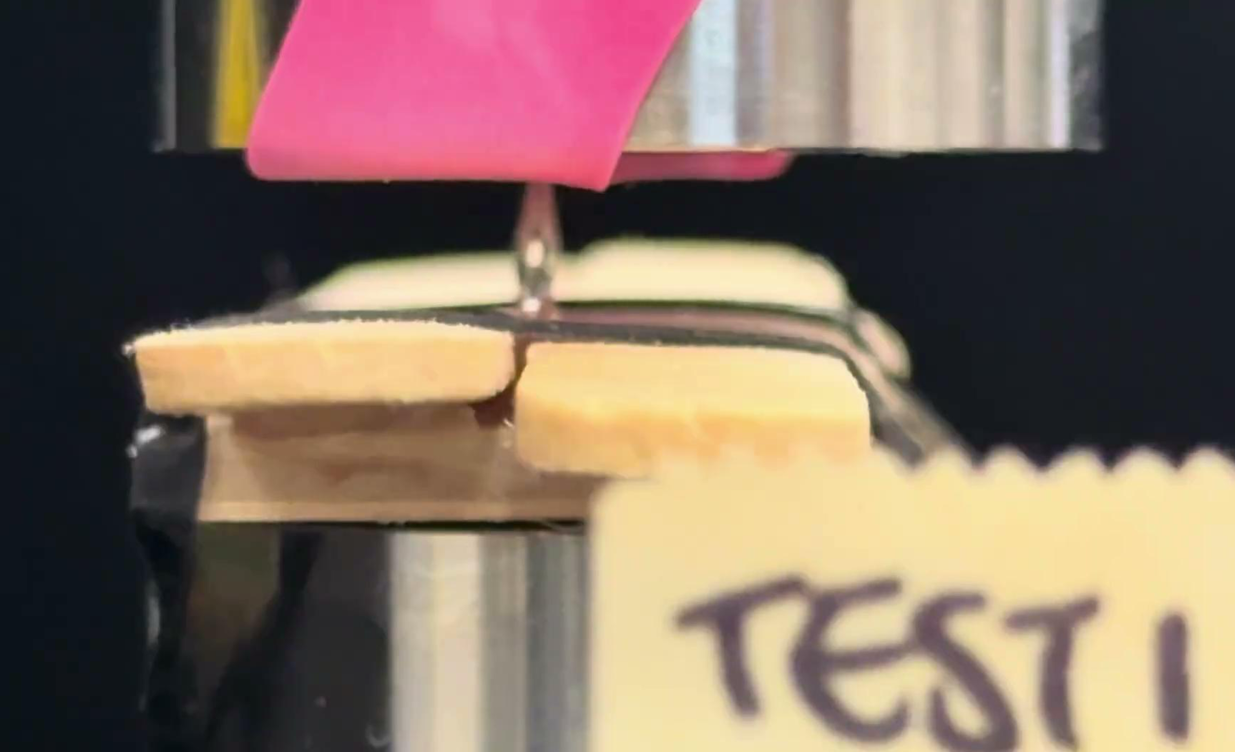
Method
The team tested three IOL materials using a custom compression rig made from popsicle-stick supports, elastic-band stabilization, and a compression plate with controlled displacement. Lens haptics were removed to avoid interference, and each lens was compressed to half its diameter (2.5 mm displacement). Force-displacement data was collected during loading and unloading, with forces kept low enough to avoid breaking the lenses. Lenses were filmed from the side to analyze bending angles and deformation behavior. The data was averaged across trials to compare stiffness, bending capacity, and non-linear deformation behavior. Special attention was given to wrinkling behavior in hydrophilic acrylic lenses and how it changed when submerged in water.
Solution
Results showed that PMMA tolerated the highest compressive forces (~27 N) but exhibited the least bending ability, meaning it requires the largest incision. Both hydrophobic and hydrophilic acrylic lenses showed much lower force thresholds (~2 N), indicating far greater flexibility. Hydrophobic acrylic displayed the most controlled and effective bending, making it the best option for minimizing incision size (over 2 mm of reduction). Hydrophilic acrylic performed slightly worse (1.5 mm reduction) but demonstrated unique wrinkling and shape-memory-like behavior that merits further investigation. Overall, hydrophobic acrylic is the optimal material for reducing incision size, though clinical considerations such as cost, surgeon experience, and biocompatibility must also be factored in.


Competitions
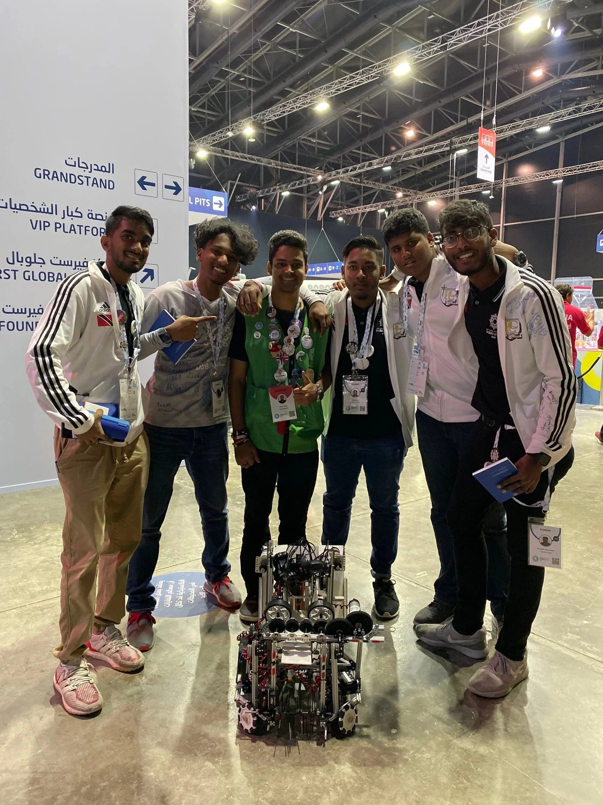
FIRST Global Challenge, Team TTO 2019
The FIRST Global Challenge is an annual international robotics competition that brings together national teams from more than 150 countries to solve real-world problems using STEM, teamwork, and innovation. Each team designs, builds, and programs a robot to compete in a themed game reflecting global challenges such as energy, water, or sustainability. The event highlights cooperation between nations, cultural exchange, and the power of youth-driven engineering.
My Role – Jibrail Bhagwandass
As the captain of Team Trinidad and Tobago 2019, you played a central role in leading the team’s engineering vision and overall strategy. Your intuition for mechanical and systems design, combined with your ability to motivate and unify your teammates, positioned you as the technical and emotional anchor of the group. You guided robot development, coordinated problem-solving efforts, and ensured the team performed at a high standard while representing Trinidad and Tobago on the world stage.
https://first.global/2019-nations/trinidad-and-tobago-2019/

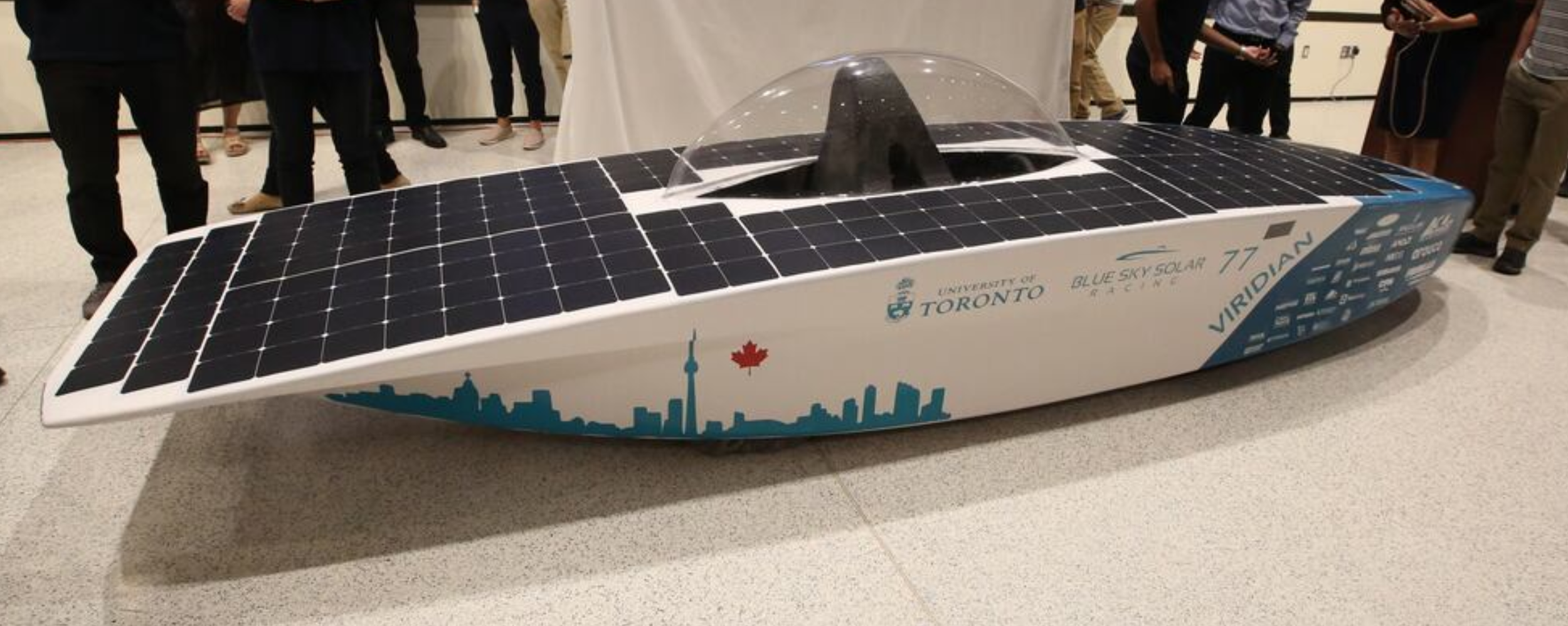
Blue Sky Solar Racing 2023
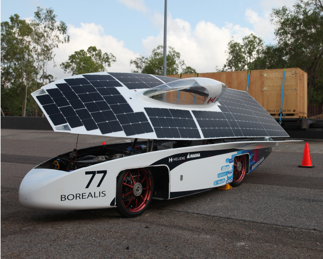
Blue Sky Solar Racing is a student-led engineering team at the University of Toronto, founded in 1995. With over 50 members from diverse academic backgrounds, the team designs, builds, and races solar-powered vehicles, pushing the boundaries of renewable energy and sustainable transportation. Their two-year development cycle culminates in competing at major events like the World Solar Challenge, a 3,022 km race across Australia. Beyond engineering, the team focuses on education, innovation, and outreach—training new members from scratch, connecting with the community, and maintaining a strong media presence. Over 300 students have contributed to the team’s legacy of technological advancement and hands-on learning
My Role – Jibrail Bhagwandass
As a member of the structural and fabrication team I took part in both design of the vehicle and creation of it. More specifically I was apart of the design of the roll cage and canopy. In fabrication, I layered the carbon fibre epoxy composited for the top aero-body and roll cage/ seat. I also layered the fibre glass to create the mold for the thermo-plastic canopy .
https://www.blueskysolar.org/index